1
/
of
6
Geek Barn
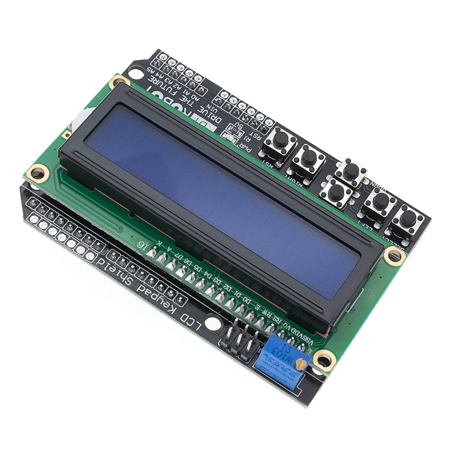
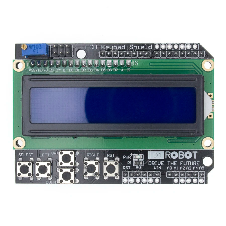
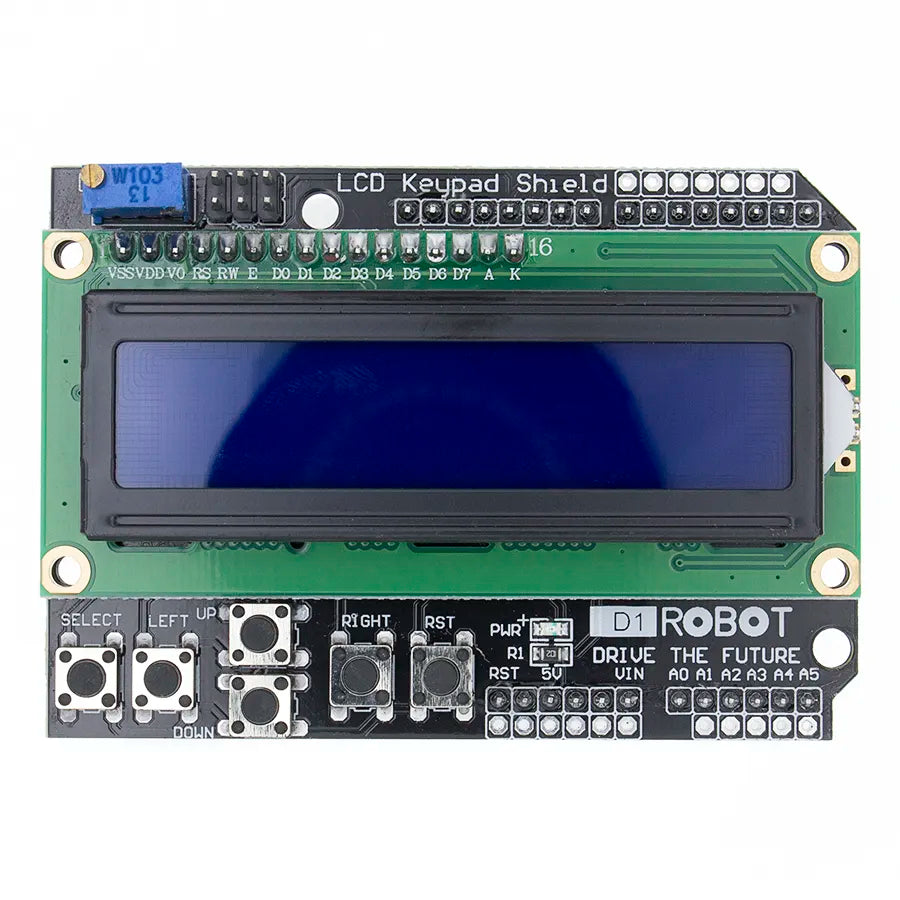
LCD Keypad Shield LCD1602 LCD 1602 Module Display blue screen For Arduino
LCD Keypad Shield LCD1602 LCD 1602 Module Display blue screen For Arduino
Regular price
$8.06 AUD
Regular price
Sale price
$8.06 AUD
Unit price
/
per
Tax included.
Couldn't load pickup availability
SPECIFICATIONS
Brand Name: TENSTAR ROBOT
Origin: Mainland China
Model Number: LCD1602
Resolution: 16*2
Type: Character
Display Mode: 1
is_customized: Yes

1602LCD Main technical parameters:
1. Display capacity: 16 × 2 characters
2. Chip operating voltage: 4.5-5.5V
3. Operating Current: 2.0mA (5.0V)
4. Module best working voltage: 5.0V
5. Character size: 2.95 × 4.35 (W × H) mm

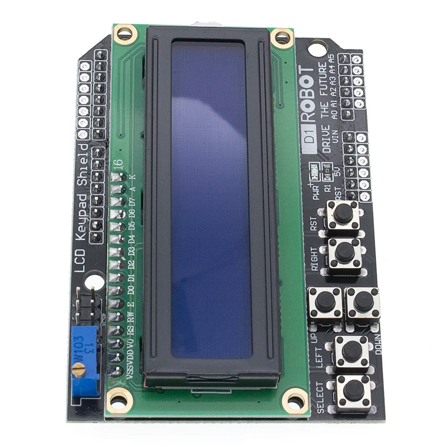
Pin Definitions:
1 VSS Power Ground 9 D2 Data
2 VDD Power Positive 10 D3 Data
3 VL liquid crystal display bias 11 D4 data
4 RS Data / Command Select 12 D5 data
5 R / W R / W Selects 13 D6 data
6 E Enable signal 14 D7 data
7 D0 Data 15 BLA Backlight Positive
8 D1 Data 16 BLK Backlight negative
1 feet: VSS for the ground power.
2 feet: VDD 5V power supply is connected.
3 feet: VL for LCD contrast adjustment side, then the power supply is the weakest contrast, grounding contrast
Maximum, high contrast will produce "ghosting", can be used when a 10K potentiometer to adjust the contrast.
4 feet: RS for the register selection, select the high data register, low when the instruction select register.
5 feet: R / W for the read and write signal lines, high when the read operation, low when the write operation. When RS
And R / W together for the low level can be written to the instruction or display address, when the RS is low when the R / W is high
Can read busy signal, when RS is high level R / W is low level can write data.
6 feet: E-side is enabled, when the E-level jump from high to low, the LCD module to execute the command.
7 to 14 feet: D0 ~ D7 for the 8-bit bi-directional data lines.
15 feet: backlight cathode.
16 feet: backlight negative.
1602LCD the instructions:
1602 LCD module internal controller a total of 11 control instructions, as shown in the table below:
No. Instruction RS R / W D7 D6 D5 D4 D3 D2 D1 D0
1 Clear screen 0 0 0 0 0 0 0 0 0 1
2 Cursor Return 0 0 0 0 0 0 0 0 1 *
3 Set input mode 0 0 0 0 0 0 0 1 I / D S
4 Display On / Off Control 0 0 0 0 0 0 1 D C B
5 Cursor or character shift 0 0 0 0 0 1 S / C R / L * *
6 Set Function 0 0 0 0 1 DL N F * *
7 Set character generation memory address 0 0 0 1 Character generation memory address
8 Set data memory address 0 0 1 Display data memory address
9 Read busy flag or address 0 1 BF counter address
10 Write to CGRAM or DDRAM) 1 0 Data to be written
11 Read data from CGRAM or DDRAM 1 1 Read the data contents
1602 LCD module read and write operations, the screen and cursor operations are programmed through the instructions to achieve. (Note: 1 is high, 0 is low)
Instruction 1: Clear display, instruction code 01H, cursor reset to address 00H.
Command 2: The cursor is reset and the cursor returns to address 00H.
Instruction 3: Cursor and display mode setting I / D: Cursor moving direction, high level shifting to the right, low level moving left S:
All text on the screen moves left or right. High level means active, low level is invalid.
Command 4: Display switch control. D: control the overall display on and off, said high-open display, low power
Flat display off display C: control cursor on and off, high means that there is a cursor, low level that no cursor B: control
Whether the cursor is flashing, high level flashing, low level does not flicker.
Instruction 5: Cursor or display shift S / C: Moves the displayed text at high level, and moves the cursor at low level.
Instruction 6: Function setting command DL: 4-bit bus at high level, 8-bit bus at low level N: Low power
Usually single-line display, high-level double-line display F: low level display 5x7 dot matrix characters, high level display
5x10 dot matrix characters.
Command 7: Character generator RAM address setting.
Instruction 8: DDRAM address setting.
Instruction 9: Read busy signal and cursor address BF: Busy flag, high level means busy, then module can not connect
Command or data received, if the low level that is not busy.
Command 10: Write data.
Command 11: Read data.
Compatible with the HD44780 chip timing table is as follows:
Read status input RS = L, R / W = H, E = H Output D0-D7 = Status word
Write command input RS = L, R / W = L, D0-D7 = Instruction code, E = High pulse output None
Read data input RS = H, R / W = H, E = H output D0-D7 = data
Write Data Inputs RS = H, R / W = L, D0-D7 = Data, E = High Pulse Output None
1602LCD general initialization (reset) process:
Delay 15mS
Write command 38H (do not detect busy signal)
Delay 5mS
Write command 38H (do not detect busy signal)
Delay 5mS
Write command 38H (do not detect busy signal)
After each write command, read / write data operations need to detect busy signal
Write command 38H: Displays the mode setting
Write command 08H: Display is off
Write command 01H: Display clear screen
Write command 06H: Displays the cursor movement setting
Write command 0CH: Display ON and cursor setting
AUDUINO official routine:
// example use of LCD4Bit_mod library
#include <LCD4Bit_mod.h>
// create object to control an LCD.
// number of lines in display = 1
LCD4Bit_mod lcd = LCD4Bit_mod (2);
// Key message
Char msgs [5] [15] = { "Right Key OK",
"Up Key OK",
"Down Key OK",
"Left Key OK",
"Select Key OK"};
Int adc_key_val [5] = {30,150,360,535,760};
Int NUM_KEYS = 5;
Int adc_key_in;
Int key = -1;
Int oldkey = -1;
Void setup () {
PinMode (13, OUTPUT); // we'll use the debug LED to output a heartbeat
Lcd.init ();
// optionally, now set up our application-specific display settings, overriding whatever the lcd did in lcd.init ()
//lcd.commandWrite(0x0F);// cursor on, on on, blink on. (Nasty!)
Lcd.clear ();
Lcd.printIn ( "KEYPAD testing ... pressing");
}}
Void loop () {
Adc_key_in = analogRead (0); // read the value from the sensor
DigitalWrite (13, HIGH);
Key = get_key (adc_key_in); // convert into key press
If (key! = Oldkey) // if keypress is detected
{
Delay (50); // wait for debounce time
Adc_key_in = analogRead (0); // read the value from the sensor
Key = get_key (adc_key_in); // convert into key press
If (key! = Oldkey)
{
Oldkey = key;
If (key> = 0) {
Lcd.cursorTo (2, 0); // line = 2, x = 0
Lcd.printIn (msgs [key]);
}}
}}
}}
// delay (1000);
DigitalWrite (13, LOW);
}}
// Convert ADC value to key number
Int get_key (unsigned int input)
{
Int k;
For (k = 0; k <NUM_KEYS; k ++)
{
If (input <adc_key_val [k])
{
Return k;
}}
}}
If (k> = NUM_KEYS)
K = -1; // No valid key pressed
Return k;
}}
LCD4Bit_mod.h

Share

