


Geek Barn
1pcs TM1637 4 Bits Digital LED Display Module For arduino 7 Segment 0.36Inch Clock RED Anode Tube Four Serial Driver Board Pack
1pcs TM1637 4 Bits Digital LED Display Module For arduino 7 Segment 0.36Inch Clock RED Anode Tube Four Serial Driver Board Pack
Couldn't load pickup availability
SPECIFICATIONS
Brand Name: AITEWIN ROBOT
Origin: Mainland China
Tube Chip Color: Red
Model Number: 4 Bits Digital Tube LED Display Module
is_customized: Yes
Display Function: digital
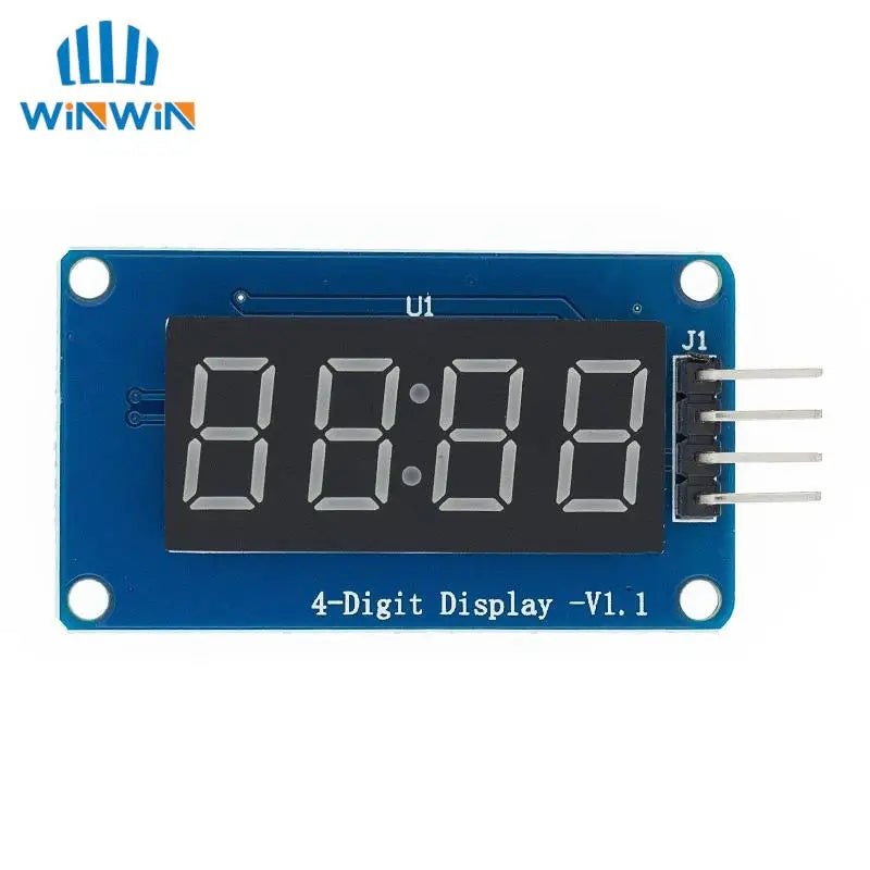
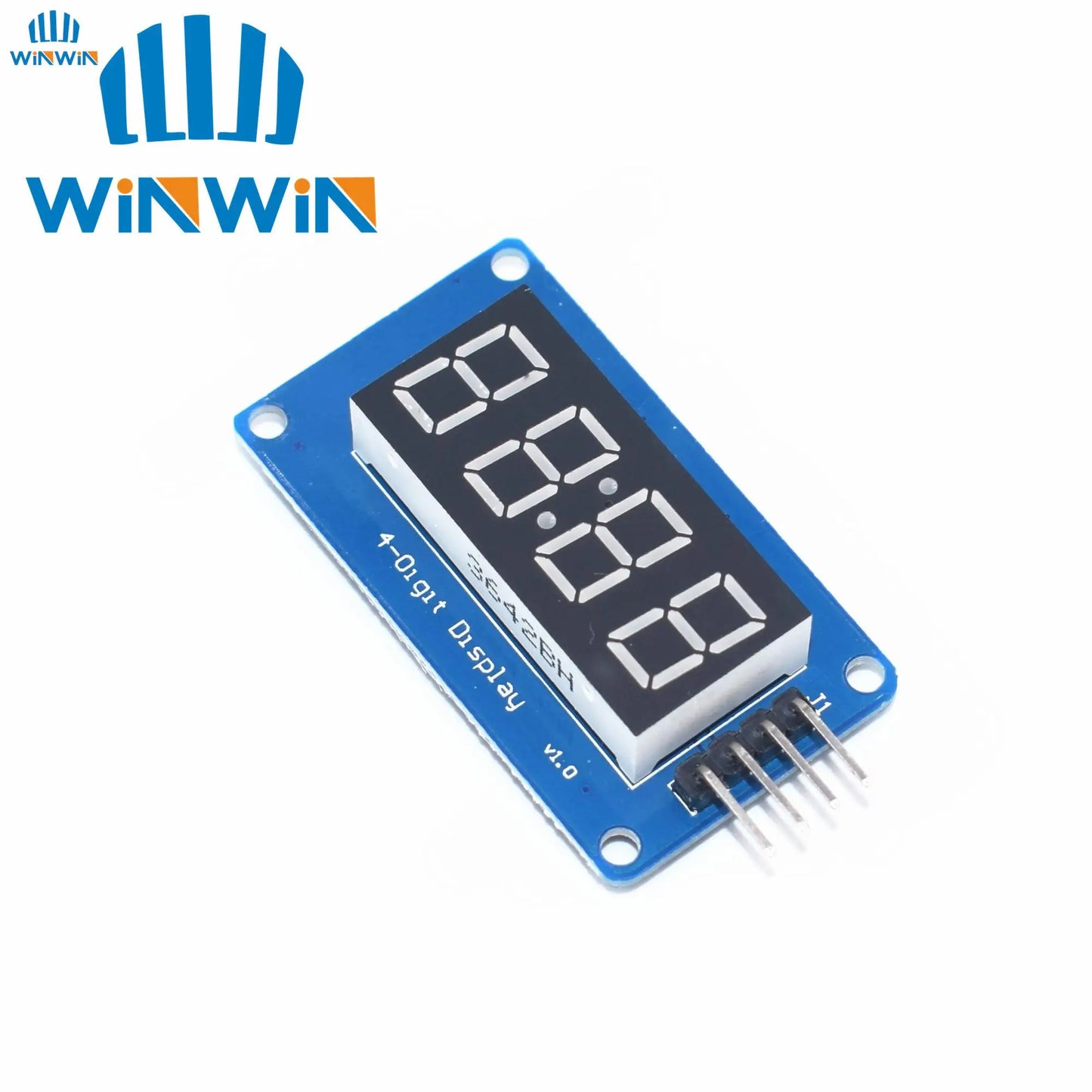
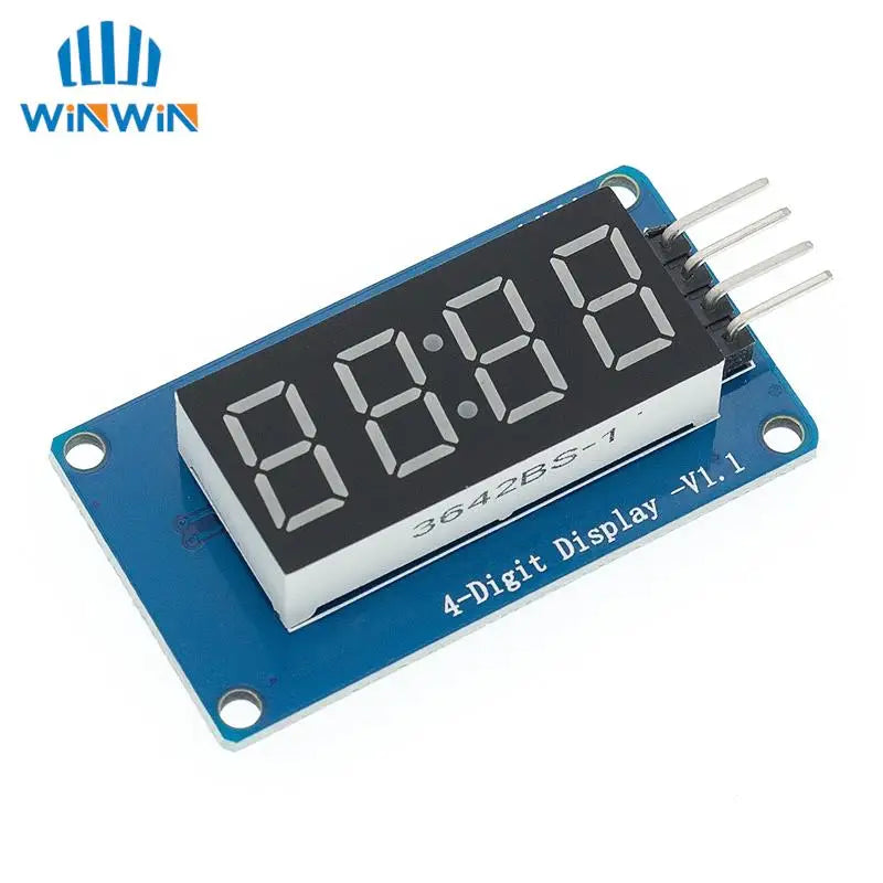
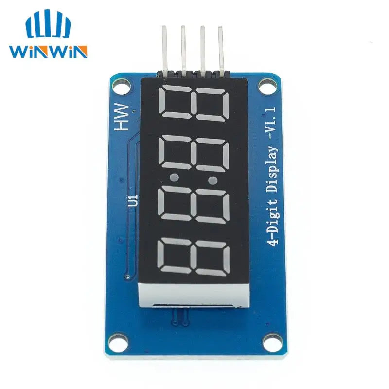
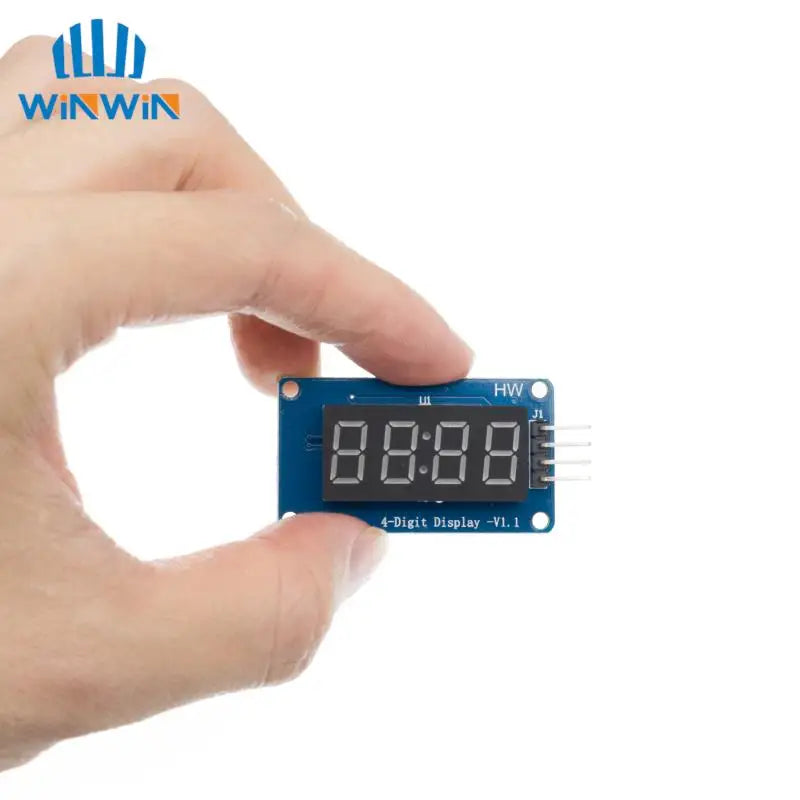
The module is a 12-pin display module with a 4-point common digital tube (0.36 inch) with a clock point. The driver chip is TM1637. It only needs 2 signal lines to enable the MCU to control the 4-bit 8- Segment digital tube.
The module features are as follows:
Display device is 4-digit yang red digital tube
Digital tube 8-level grayscale adjustable
Control interface level can be 5V or 3.3V
4 M2 screw positioning holes for easy installation
Project |
Minimum value |
Typical value |
Maximum |
Unit |
Voltage |
3.3 |
5 |
5.5 |
VDC |
Current (@5V) |
- |
30 |
80 |
mA |
Size |
42X24X12 |
Mm |
||
Weight |
8 |
g |
||
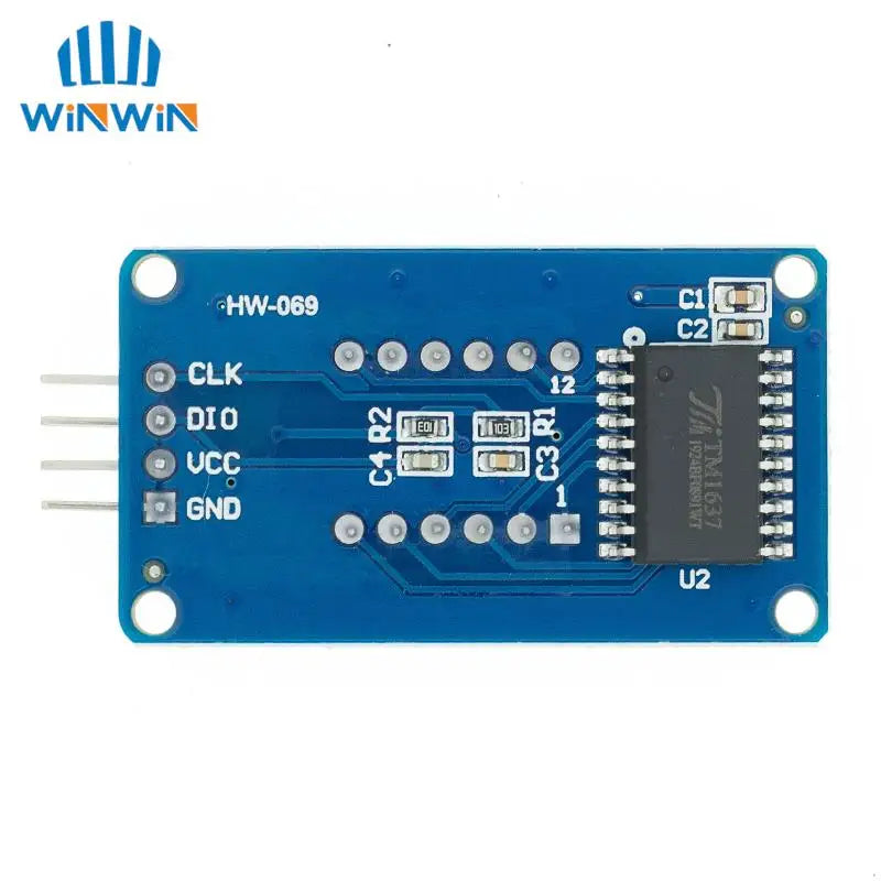
Control interfaceA total of 4 pins (GND, VCC, DIO, CLK), GND is ground, VCC is the power supply, DIO is the data input and output pin, CLK is the clock signal pin;
Digital Tube: 4-digit common anode with a 0.36-inch digital tube with a score point, highlighted in red;
Positioning hole: 4 M2 screw positioning holes, the hole diameter is 2.2mm, which makes the module easy to install and position, and realize the module combination;
Overview of the library routines:
1. ClockDisplay: Use the timer 1 of the MCU on the motherboard to time and let the 4-digit display display.
2. NumberFlow: 0~9, A, b, C, d, E, F and other 16 characters flow from right to left.
3. StopWatch: Use the timer 1 of the MCU on the motherboard to time, and use the button to realize the stopwatch function.
Experiment equipment:
An Ard uino compatible motherboard Cat duino (not familiar with open source hardware can be understood as the Atmega328P microcontroller development board) and a mini USB cable;
1 4-digit digital tube display module;
4 male to female DuPont lines for connecting the control interface of the module and the Cat duino development board;
Experimental procedure:
1. Use 4 male to female DuPont lines 4-digit digital display module Connected to Cat duino, as shown in the following table and figure
Cat duino |
Cable |
4-digit digital display module |
GND |
black line |
GND |
5V |
Red line |
VCC |
D2 |
Yellow line |
DIO |
D3 |
White line |
CLK |
2. Connect the Catduino with mini USB. If you are using the motherboard for the first time, its USB to serial driver can find the USB Drivers from the drivers in the Ard uino IDE directory.
3. Reopen the Ard uino IDE and click the Open button on the toolbar to open the NumberFlow routine in DigitalTube.
Select the serial port, board name, click the Burn button, you can burn. This routine can make 16 characters from 0~9, A, b, C, d, E, F, etc. flow from right to left.
The function of adjusting the gray scale of the digital tube is the set() function in the class TM1637, and the input parameter is 0~7. The larger the number, the higher the brightness.
Share